
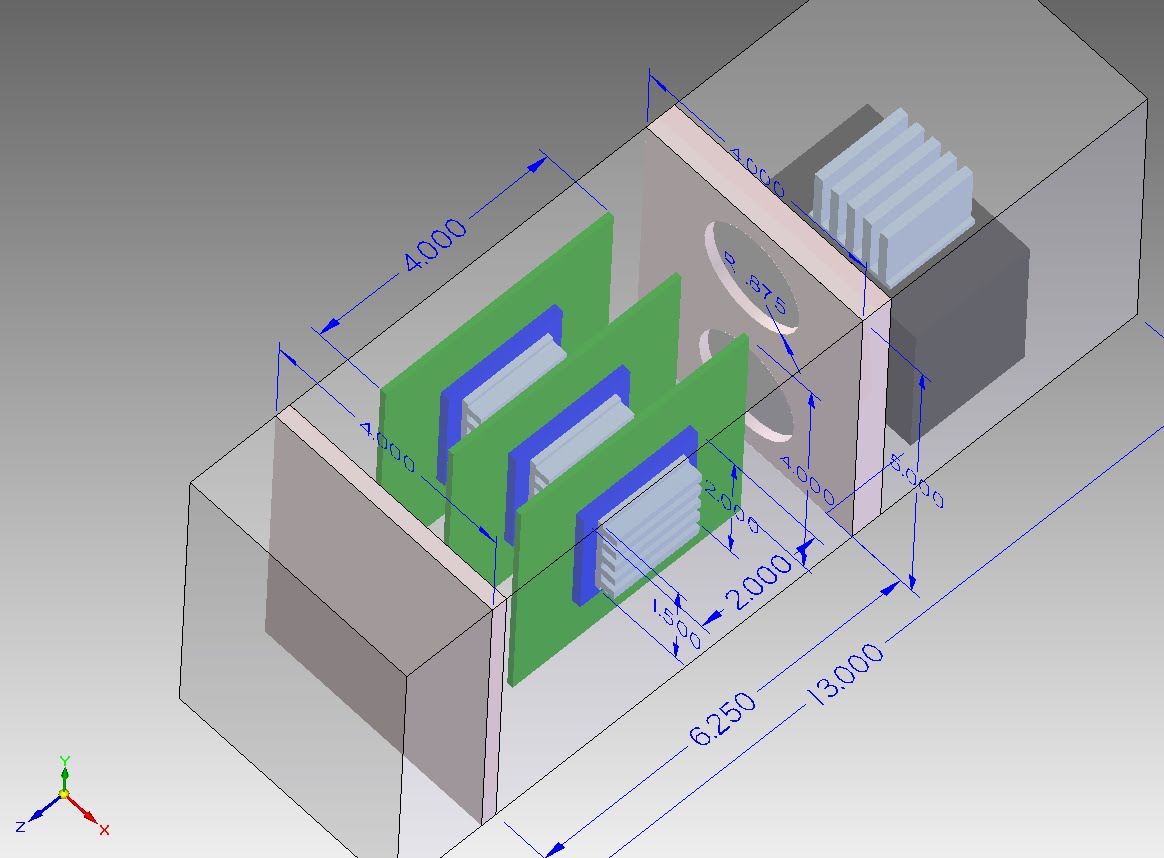
Assume a casing of size 6.25in X 4.0in X 5.0in with two internal fans (R=0.875in) is used to house three units of electronic chips that are lined up side by side (please see the graph). The casing has two end plates. The first end plate houses two internal fans that are stacked on top of each other (inlet), while the second end pate is perforated to allow the air to pass through (outlet). Each fan supplies the air at the volume flow rate of 10 ft^3/min (CFM). Each chip dissipates power at 10 Watts, and it is connected to a PCB (printed circuit board) and an aluminum heat sink. Please refer to the graph for dimensions (all dimensions are in inches).
The first step of the CFD procedure will be solving for the air flow distribution assuming,
1) no-slip boundary conditions at the solid surfaces
2) the flow is assumed to be viscous, incompressible flow (Mach number <0.3)
3) The chip dissipates heat at 10 Watts.
Material Properties
1) The PCB is a composite structure and anisotropic (i.e. the material properties are different in different axes):
Through-Plane Thermal Conductivity = 0.00847611 W/in-K
In Plane Thermal Conductivity = 2.1757 W/in-K
Density = 4.04376E-5 lbf-sec^2/in^4
Specific Heat = 146713 W-in/lbf-s-K
2) The Chip is isotropic:
Thermal Conductivity In All Directions= 0.019812 W/in-K
Density = 2.52419E-4 lbf-sec^2/in^4
Specific Heat = 147239 W-in/lbf-s-K
3) The Aluminum Heat Sink is isotropic:
Thermal Conductivity In All Directions=5.1816 W/in-K
Density = 2.53074E-4 lbf-sec^2/in^4
Specific Heat = 157054 W-in/lbf-s-K

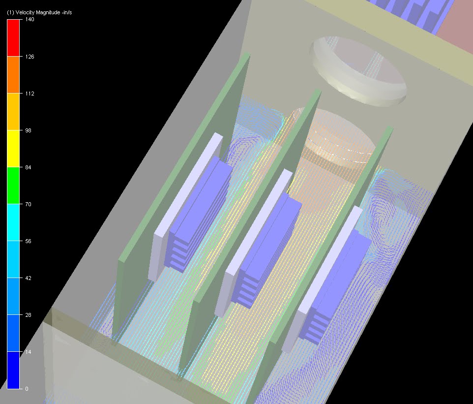

The CFD solves for the air flow distribution, and the results are described below:
1) The first thing to notice is the formation of Eddie current in the corners of the casing. The Eddie current creates a recirculation zone that essentially "blocks" the incoming air. As a result, the air is forced to flow into the space in between the chips before it loops around them near the ends of the PCBs (Please see the animated video).
2) The chip in the center has the best flow rate among the three as the air is directly blown across its surface at high velocities on both sides - 70 to 112 in/sec.
3) The chip in the right side has good flow rate on the backside of the PCB board (40 in/sec) but not on the heat sink side (20 in/sec) as the air needs to flow around the PCB before it can reach the heat sink.
3)The chip in the left side has low flow rates on both the heat sink side (56 in/sec) and the PCB side (14 in/sec).
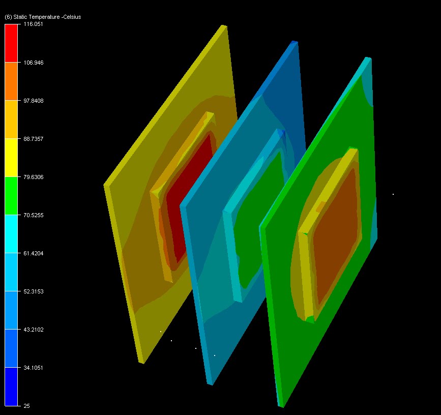
The second step of the CFD procedure is to solve for the temperature distribution based on the flow velocity distribution obtained in the first step. The flow is essentially advecting heat from the surfaces of the electronic parts. The results are shown below:
1) The chip in the center (coolest) is at 75 degC while its PCB is at 56 degC.
2) The chip in the right is at 101 degC, while its PCB is at 75 degC.
3) The chip in the left is at 111 degC, while its PCB is at 89 degC
No comments:
Post a Comment